555 counter inverter circuit uses MOSFET
Do you want to learn more about this simple inverter circuit? It only needs a few components to produce a total of 50 watts of power.
This is a 555 IC inverter circuit because it mainly uses a 555 timer and MOSFET. I tried it, and it works great.
When using a 12V battery as a power source, it will output 220V AC at 50Hz.
Basic principles of the circuit:
We believe most people dislike reading lengthy and tedious explanations. Therefore, for simplicity, we recommend understanding the simple principle of the inverter.

Initially, the DC voltage from the battery enters the square wave oscillator circuit (50Hz oscillator), creating a 50Hz AC voltage. However, the current is too low.
Here's the corrected version of the paragraph:
Initially, the DC voltage from the battery enters the square wave oscillator circuit (50Hz oscillator), creating a 50Hz AC voltage. However, the current is too low.
What can be done to increase the current?
In this case, power switches (AB switches) such as power transistors or MOSFETs are a good choice.
But is the AC voltage still 12V? The inductance of the transformer will increase the voltage to 220V AC at 50Hz, ready to supply to the load.
Working principle of the 555 inverter circuit
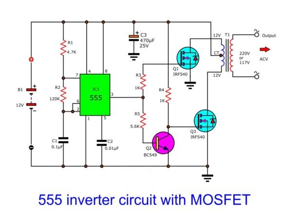
The circuit below is the complete circuit diagram for this project. The IC-NE555 timer I used is a square wave frequency generator with a 50Hz output.
The frequency is determined by resistor R2 and capacitor C1.
Calculate the output frequency of the 555.
If your R2 is 150K, then the output is 47Hz. You can add a potentiometer and fine-tune it to 50Hz later.
MF4Me says: By calculation (results will vary based on parts tolerances), a good combination of common parts would be:
0.2 μF (2 x 0.1 parallel).
R1 is 100Ω.
R2 is 72K (39K and 33K series).

The calculation result is 50.069 Hz, and the duty cycle is 50.03%. This demonstrates smart precision. If its tolerance is lower.
Even? We use N-type IRF540 MOSFETs (Q2, Q3) to drive the transformer winding (primary winding).
The output current from pin 3 of IC1 will flow in two directions.
First, it goes through R3 to gate Q2.
Second, the current to transistor Q1 BC549 acts as an inverter logic to invert the first signal difference.
Next, current flows to gate Q3, which also drives the transformer.
It senses low voltage to high voltage, ranging from about 220V to 250V, depending on the battery (12V to 14.4V).
MOSFET inverter circuit diagram
For the transformer, if the input voltage is 12V, then I use 2A current. The result is power output in excess of 100 watts.
In the circuit, we use MOSFET IRF540. There are many reasons to use them.
They are very easy to use. They do not require pre-driver transistors in Darlington configurations, like conventional transistors such as TIP41, 2SC1061, etc.
They can drive high current loads, up to 27A. The TIP41 transistor can only drive a 4A load.
They are inexpensive, costing only $0.80 per unit.
Their body is similar to that of the TIP41 transistor, so they are easy to attach to the heatsink.
Because they produce less heat, they can be mounted on smaller heatsinks than transistors.
Ingredients list:
- IC1: NE555 timer IC = 1 piece.
- Q1: Transistor BC549-NPN 40V 0.5A = 1 piece.
- Q2, Q3: N-channel power MOSFET IRF540, 100V, 27A, TO-220 = 2 pieces.
- C1, C2: Polyester film capacitors 0.1uF 100V = 2 pieces.
- 0.5W resistor.
- R1: 4.7KΩ = 1 piece.
- R2: 120KΩ = 1 piece.
- R3, R4: 1KΩ = 2 pieces.
- R5: 5.6KΩ = 1 piece.
- T1: 2A 12V CT 12V transformer = 1 piece.
- Radiators.
Related: Inverter circuit diagram—TL494 inverter circuit
Check everything for errors.
🔹 Version from Nikola Tesla's "Magnifying Transmitter"
🔹 The "tension" for "electricity fractionation" to occur is the Earth's Potential Potential. To be precise, it is the tension of the Ether, and the electricity is the dynamic polarization of the Ether.
🔹 During "Electricity segment", the magnetic field collapses several times in short periods of time. That leads the voltage V = Φ/t to reach infinity (V → ∞) when t → 0
- V - The electromotive force which results from the production or consumption of the total magnetic induction Φ (Phi). The unit is the “Volt”. Where t is the time of magnetic field collapse from maximum to complete collapse.
- Research scholars also call it Tesla's technology called Radiant Energy from Electronic Circuits, Impulse Technology.


