Radiant Energy from the Sky: Power from an Aerial
Overview of Ether technology harnesses the potential between the earth and the sky - creating free energy
There are two basic methods for this (exploiting electricity from the ground and the sky):
- Ether's electro-elastic oscillation fish resonance method uses ultra-high frequency for mining. This is Nikola Tesla's technology [1].
- The remaining method is commonly found in the Tartarian empire (the history of Tartaria is hidden from official documents): Exploiting the electrostatic potential between the ground and the sky. In this article, we will discuss and guide you about this method. [2]
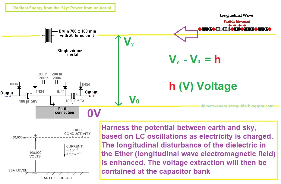
Essentially, this method exploits the voltage difference between the ground and the sky voltage. Here is information from mainstream science [3]:
- 1/ Over a flat field on a day with clear skies, the atmospheric potential gradient is approximately 120 V/m.
- 2/ The total voltage between the earth and the ionosphere is difficult to measure instantaneously, but many groups have estimated the voltage to be 250-350 kV using a variety of techniques. Experimentally, we know that the earth carries a net negative charge compared to the upper atmosphere/ionosphere.
- 3/ By about 50 kilometers, the field is very small, so most of the potential change (the integral of E) is at lower altitudes. The total potential difference from the surface of the earth to the top of the atmosphere is about 400,000 volts.
- 4/ The atmospheric electric field near the earth's surface in fair weather conditions is about 100 to 300 V/m.
- 5/ Thus there is a vertical electric field E of 100 volts/m in the air. The sign of the field corresponds to a negative charge on the earth's surface. [ Chalmers, J. Alan, Atmospheric Electricity, Pergamon Press, London (1957).]
The LC circuit consists of capacitor C and inductor L, which are connected in series, parallel, or in combination.
2 LC electrical oscillation circuits. These two electrical oscillations are promoted, resonate, and support each other through 200V capacitors facing each other.
The boost is based on LC oscillation and is strongest when the 50V capacitors are fully charged.
The upper Ether field, at the axis of the coil, where the dielectric loses inertia is captured and increased by the oscillations of the LC diaphragm.
The longitudinal disturbance of the dielectric field in the Ether is enhanced by LC oscillations.
Instructions for practicing and developing (improving) Ether technology to exploit electricity between the ground and the sky
We come now to the practical and useful aerials used by Jes Ascanius, a Danish developer, to whom thanks is due for sharing his design. Initially, he set up a system to charge his mobile phone battery overnight from an aerial. Let’s start with the very simple system and progress from that to more powerful arrangements [4].
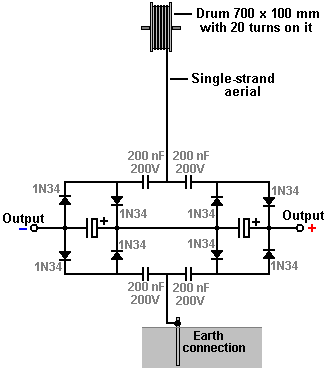
The initial circuit uses one strand of solid wire which rises vertically to a 700 mm diameter drum where there are some twenty turns. The arrangement is like this:
The aerial wire is several metres long, and in the prototype, was supported by (and insulated from) the eaves of a house. The aerial should be vertical or near vertical and a proper earth connection provided by driving a metal rod into the ground or connecting a wire to a metal plate and burying the plate in the ground as a good electrical connection is needed here. The earth connection used here is a 12 mm copper pipe 3 metres long, driven into the ground and the ground around it saturated with water:
The wire used to connect with the earthing rod is very important and should not be less than 8 swg copper wire, that is, 4 mm diameter and 13 sq. mm. cross-sectional area. With this free-energy device, this is an important detail as are the diodes used which are germanium 1N34 or 1N34a which are particularly suited to this application due to their very low voltage drop. For the 200 nF capacitors, ceramic disc types are recommended. The prototype build used two large scavenged capacitors and it looks like this:
Now, consider this circuit as described, to be one modular building block which can lead to serious power being drawn from an aerial. I will represent the circuit shown above as a rectangle, showing the above circuit as:
While it is possible to use more than one module with the aerial to get more power, the Danish developer then switched to a more advanced arrangement by attaching a 600 x 800 x 2 mm aluminium plate inside the sloping roof of his house:
The plate is positioned between 3 and 3.5 metres (10 to 12 feet) above the ground and the attachment to the plate is also heavy-duty 8 swg cable:
With this arrangement a single module produces around 30 volts while the original method of connecting near the earth was giving about 26 volts with two modules. Jes Ascanius has carried out further experimentation and he states that diodes with response times under 30 milliseconds produce a greater output and he recommends the use of BYV27 diodes which have a 200-volt 25nS rating as he gets three times the output from them. He also recommends using them in Joule Thief circuits.
🔹 Version from Nikola Tesla's "Magnifying Transmitter"
🔹 The "tension" for "electrical fractionation" to occur is the Earth's Potential Potential. To be precise, it is the tension of the Ether, and the electricity is the dynamic polarization of the Ether.
🔹 During "electrical segmentation", the magnetic field collapses several times in short periods of time. That leads the voltage V = Φ/t to reach infinity (V → ∞) when t → 0
- V - The electromotive force which results from the production or consumption of the total magnetic induction Φ (Phi). The unit is the “Volt”. Where t is the time of magnetic field collapse from maximum to complete collapse.
- Research scholars also call it Tesla's technology called Radiant Energy from Electronic Circuits, Impulse Technology.
🔹 There are also many other plans to create free energy generators including Self Powered AC Generator.
Referral:
It's Even More Practical Than It Seemed 70 Years Ago…
🔻 And for the first time in human history, ordinary folks can finally power up anything they need with renewable electricity...while investing a fraction of what the inventor ever thought was possible.
💠 Revealed At Last:
👉 Ancient Invention Generates Energy-On-Demand


